555 Timer Internal Schematic / 555 Timer Ic Wikipedia
on
Get link
Facebook
X
Pinterest
Email
Other Apps
555 Timer Internal Schematic / 555 Timer Ic Wikipedia. Ic 555 timer is a one of. In this video, the brief introduction to the 555 timer ic has been given and the pin diagram (of 8 pin dip 555 ic) and the internal block diagram of the 555. It is available in 3 different packages: The second 555 timer helper will extend the timers output duration without having to use large values of r1 and/or c1. 555 timer internal circuit diagram.
In this video, i've explained 555 timer ic with the pin diagram and the internal circuit diagram. With this information you will learn how how the 555 works and will have the experience to build some of the circuits below. We can see that it us made up of 21 transistors, 4 diodes, and 15 resistors. Being an integral part of electronics project, 555 timer ic is very often used in simple to complex electronics projects. The ic 555 basically a timer ic.
Ic 555 Timer Circuits Features Working And Datasheet Ic 555 Timer from ic555timer.com 555 timer internal schematic questions thread starter jearls74; The 555 timer ic is an integrated circuit (chip) used in a variety of timer, delay, pulse generation, and oscillator applications. Timing can be anywhere from microseconds to hours. The 555 is also very versatile, and can be used. Additional • timing from microseconds through hours terminals are provided for triggering or resetting if • operates in both astable and monostable modes desired. To understand the basic concept of the timer let' s first examine the timer in block form as in figure 1. 555 internal circuit consists of three series 5k resistors connected between the vcc and gnd. This can be done by configuring the ic to act as an oscillator i.e.
In this section, we will see the working of each internal component of the 555 timer ic.
Hi everyone, i am trying to build a very high current dc to ac inverter and i cant use a 555 timer ic because they cant source or sink but a maximum of 200ma, but i have found an internal schematic of the 555 timer ic online. It can operate in both astable and monostable modes. You may already know that se/ne 555 is a timer ic introduced by signetics corporation in 1970's. In this article, we cover the following information about 555 timer ic. The internal block diagram of ic 555, you can see in the below figure the internal circuit has no. The standard 555 timer ic is made of 2 diodes. Being an integral part of electronics project, 555 timer ic is very often used in simple to complex electronics projects. Here, with the help of the 555 timer ic, we are eliminating the need of manually switching on or off the device. The 555 timer is a chip that can be us… In this circuit, we have four basic blocks, these are 1. Internal diagram of 555 timer ic. The 555 timer has two basic operational modes: In this video, the brief introduction to the 555 timer ic has been given and the pin diagram (of 8 pin dip 555 ic) and the internal block diagram of the 555.
555 timer internal circuit diagram. A chip that can act as an oscillator, a schmitt trigger, pwm driver, a siren/alarm, a light or dark detector, and much much more. Monostable 555 timer circuits will automatically trigger and start a timing cycle when power is applied to the circuit. The circuit latches in either the q state or its refer block diagram of 555 timer ic given above: It can operate in both astable and monostable modes.
555 Timer Ic Pinout Examples Circuits Different Modes Applications from microcontrollerslab.com 555 timer internal circuit operation. The 555 timer can be operated at a wide range of power supplies ranging from 5 v to 18 v. As discussed in the above section, the ic is in its standard monostable mode. The 555 timer is a chip that can be us… The circuit latches in either the q state or its refer block diagram of 555 timer ic given above: 555 timer helpers schematic the addition of a capacitor to the trigger will not work for short output pulses as there is also a short delay in the recovery of the trigger terminal voltage. The three resistors used in it are of 5kohm and they served as a voltage divider between vcc and ground. The timer's internal circuitry is largely responsible for this triggering but it is also caused stray or installed capacitance at the trigger input of the timer.
In this video, i've explained 555 timer ic with the pin diagram and the internal circuit diagram.
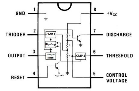
A chip so versatile that it has been used in everything from toys to spacecraft. 555 timer internal circuit operation. Derivatives provide two or four timing circuits in one package.it was commercialized in 1972 by signetics. The 555 timer can be operated at a wide range of power supplies ranging from 5 v to 18 v. Timing can be anywhere from microseconds to hours. The internal circuit of this 555 timer consists of comparators, flipflops, transistors, resistors, and output stages. Here, with the help of the 555 timer ic, we are eliminating the need of manually switching on or off the device. Internal diagram of 555 timer ic. There are a lot of applications of this ic, mostly used as vibrators like, astable multivibrator, monostable multivibrator, and bistable multivibrator. The internal block diagram of ic 555, you can see in the below figure the internal circuit has no. The second 555 timer helper will extend the timers output duration without having to use large values of r1 and/or c1. 555 internal circuit consists of three series 5k resistors connected between the vcc and gnd. This article covers every basic aspect of 555 timer ic.
555 is configured in astable mode of operation. To understand the basic concept of the timer let' s first examine the timer in block form as in figure 1. The internal block diagram and schematic of the 555 timer are highlighted with the same color across all three drawings to clarify how the chip is implemented:2. 555 timer internal schematic questions thread starter jearls74; A collection of 555 circuits using the 555 timer as an astable oscillator with different duty cycles.
Circuit Diagram 555 Timer Monostable Wiring Library from 4.bp.blogspot.com Build your own 555 timer: Additional • timing from microseconds through hours terminals are provided for triggering or resetting if • operates in both astable and monostable modes desired. In this section, we will see the working of each internal component of the 555 timer ic. The 555 is also very versatile, and can be used. The second 555 timer helper will extend the timers output duration without having to use large values of r1 and/or c1. This article covers every basic aspect of 555 timer ic. The 555 timer can be operated at a wide range of power supplies ranging from 5 v to 18 v. 555 timer internal circuit operation.
The standard 555 timer ic is made of 2 diodes.
500ms is the same as saying 0.5s so by rearranging the formula above, we get the calculated value for the resistor, r as: There are a lot of applications of this ic, mostly used as vibrators like, astable multivibrator, monostable multivibrator, and bistable multivibrator. The image shown below represents the internal schematic of a standard ic 555. The 555 timer internal circuit diagram is shown below: The circuit latches in either the q state or its refer block diagram of 555 timer ic given above: Ic 555 timer is a one of. Timing can be anywhere from microseconds to hours. Start date nov 11, 2009; 555 timer helpers schematic the addition of a capacitor to the trigger will not work for short output pulses as there is also a short delay in the recovery of the trigger terminal voltage. It is very common and mostly used ic in various circuits and schematics. Monostable 555 timer circuits will automatically trigger and start a timing cycle when power is applied to the circuit. 555 timer internal circuit operation. Today we're going to discuss about 555 timer ic or ne555.
This tutorial provides sample circuits to set up a 555 timer in monostable, astable, and bistable modes as well as an in depth discussion of how the 555 timer works and how to choose components to use with it 555 timer schematic. The timer's internal circuitry is largely responsible for this triggering but it is also caused stray or installed capacitance at the trigger input of the timer.


Comments
Post a Comment